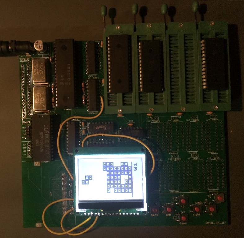
The final product.
For my 11th grade history class, our final assignment was an open-ended research project, where both the topic and the medium of presentation was up to us. Having recently watched a YouTube video about Tetris, a game invented in the Soviet Union, I instantly knew I wanted to look into computer technology in the Soviet Union during the Cold War.
However, as I begun my research, I realized that the components used at the time were still available from sites like eBay. So, I decided, instead of writing a paper, to buy some of these components and try to build a replica computer, staying as period-accurate as I reasonably could.
This post is going to talk about the more technical and electrical side of things; if you want to learn more about the historical aspects of the project, you can read the written component that I submitted with the project.
Getting the components

Soviet SRAM and EPROM chips.
The first decision I had to make was what I was going to use for the CPU of the computer. Eventually, I settled on the U880, an East German clone of the Zilog Z80, which I chose primarily due to ease of interfacing with the chip and my own familiarity with its architecture.
Once I had chosen the CPU, the peripheral chips were pretty logical choices. The Western parts that would normally be used with a Zilog Z80 all had Soviet equivalents. In the end, I chose to use a KR580VV51A (equivalent to an Intel 8251A) chip to give the computer a serial port, and a KR580VV55A (equivalent to an Intel 8255A) to handle the button inputs.
I then needed to have some sort of decoding logic. This is what coordinates the different peripheral devices on the data bus, so that they aren’t all trying to talk to the CPU at the same time. For this, I used an East German-manufactured V4028 chip (equivalent to the West’s CD4028) combined with a Soviet K155LN1 (a NOT gate, equivalent to the West’s SN7404).
For the display output, I had to cheat a little bit. Rather than connecting the system to an old analog CRT display, which would have been too bulky to transport and made the circuitry more complex, I chose to instead use a modern LCD display, connected to the rest of a system by a modern-day level shifting chip.
In addition, I originally wanted to include a CompactFlash socket, so that the computer would have some way of saving data (this would have been an imitation of the analog cassette records used at the time); unfortunately, I didn’t get the footprint for the socket correct, so I ended up abandoning that idea.
I also used three buffer chips (two for the address lines and one for data) because I was worried that I had too many chips on the same lines. These buffer chips are modern-day Texas Instruments parts, but it’s likely that they could be removed without any issues—they were only put in out of excessive caution.
Designing the computer

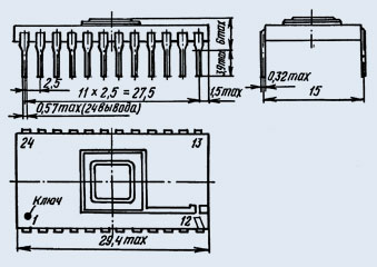
Note the 2.5 mm spacing between pins. Source

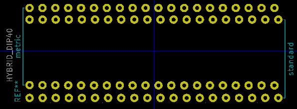
An example of a dual footprint.
Once I had decided on the components I wanted to use, I drew a schematic in KiCad. (you can see the final schematic here) Given the similarities between the Western and Eastern parts, there were many cases where I could just use KiCad’s built-in symbols. For example, even though the U880 is an East German part, it shares the same pinout as a Western Z80 chip, so I just used the pre-made Z80 symbol.
Something I quickly realized would be an issue with the Soviet components was that, despite appearing to be a normal DIP package, they actually have a slightly different pin spacing! Where most Western chips have a 0.1” (2.54 mm) pin pitch, these Soviet parts had a 2.5 mm pitch. While this difference of 0.04 mm might not seem like much, on some of the large 40-pin parts, this inaccuracy could add up. For parts that were socketed, like the CPU, I was able to just force the pins into a generic 0.1” socket. (this worked even for the large U880 CPU; however, if you look very closely, you can tell that the pins at the bottom of the part don’t line up very well with the socket—fortunately, they still make contact) However, for certain chips, I decided to instead forgo the socket, designing a special footprint with both 2.5 mm and 2.54 mm pin spacing. That way, I could easily fit the Soviet part, and still be able to swap a Soviet part with a Western equivalent if it were necessary.
Assembling the PCBs
As I was bringing up the computer, I kept running into issues where the CPU wouldn’t read from the ROM correctly, executing what seemed like completely random instructions. Eventually, after lots of debugging, I realized that the issue was with the Soviet EPROMs I had bought—for some reason, though they appeared to work fine in the TL866 I used to program them, they would return what seemed like random data when run in the computer. Eventually, I had to replace them with modern parts.
In retrospect, after looking more closely at the datasheet for the part, I realize now that the programming voltage is actually specified to be 24.5 volts, while my programmer maxed out at 21.5 volts. My guess for what happened is that somehow, the lower programming voltage meant that the EPROM still could work in the programmer, but when pushed to a faster speed in the actual computer, it stopped working. However, I can’t really find much information on the Internet about what happens when you undervolt an EPROM’s programming voltage, so it’s also possible I just received bad parts.
The final product

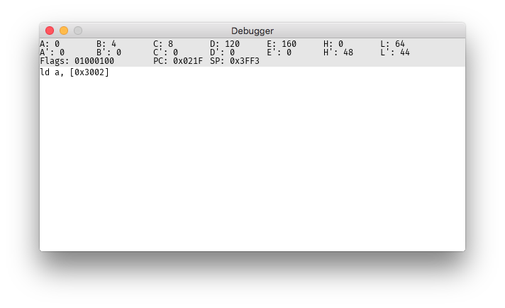
The debugger I wrote.
Finally, I had to program the computer. I had previously written an assembler for the Nintendo Gameboy, which uses a processor that’s very similar to the Z80. So, I adapted this code into z80asm, a rather minimalistic Z80 assembler targeted specifically at this computer. I also wrote an emulator for the system, complete with a (very bare-bones) debugger, which was incredibly helpful. The firmware is entirely written in Z80 assembly language, and is open-source if you want to look at it.
Ultimately, I found this project to be incredibly interesting and rewarding. I learned a lot, both in a historical and a technical aspect, and have created something that I’m proud of. All of the design and software behind the computer have been published under various GitHub repositories, as linked above.